The electronic products in our daily life all use single-cell lithium-ion batteries. How to better protect your battery is a problem that many people are concerned about. Simply focusing on how to charge the battery is far from enough. You also need to know how to protect the battery specifically. Charging control and battery protection are both indispensable.
This guide teaches you how to design a practical charging circuit and analyzes the battery protection board in depth, giving you a comprehensive understanding from theory to practice.
Table of Contents
ToggleNecessity of lithium polymer battery protection
Each lithium battery is inseparable from key parameters such as voltage, capacity and rate. The voltage range of a single battery is 3V ~ 4.2V; capacity represents how much energy the battery can store, which is directly related to how long the device can work and also affects the charging time. C rate is a relative unit, mainly used to describe the charging and discharging speed. For example, a 2C 1Ah battery can have an operating current of up to 2A. These are the main basis for the design of battery protection boards.
Lithium batteries are dangerous goods, and they have risks such as overcharge, over discharge, over current, and short circuit. This is also a problem that everyone is worried about, so it is understandable that it requires multiple protection measures.
The charging circuit is mainly used to actively manage and control the charging process. It requires the ability to accurately execute CC/CV charging strategies to ensure safe and efficient charging of the battery. In the constant voltage charging stage, it can actively reduce the current to slow down charging.
The protection board (PCM) is more of a passive detection of battery status and a fuse for charging batteries. It monitors voltage, current, and temperature changes at all times. Once an abnormality is detected, it can immediately cut off the connection between the battery and the external load to prevent a disaster.
The charging circuit and the protection board complement each other and are indispensable. The charging circuit ensures the correctness of daily charging, while the protection board provides the ultimate guarantee for dealing with abnormal situations.
Battery protection board details
Our commonly used lithium polymer battery protection board configuration is G3J chip and 8205A Mosfet. The following is the specific schematic diagram.
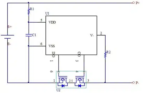
The protection IC acts as the brain of the protection board, and the Mosfet acts as the execution switch. The following is the principle of achieving key protection:
Overcharge protection: When the voltage reaches the 4.25V threshold, it sends a high-voltage signal to let MOSFET shut down the charging line and prevent current from continuing to flow into the battery.
Over-discharge protection: Similarly, when the voltage reaches 2.5V or 3V, it sends a voltage signal to control the 8205A to shut off the discharge path to prevent the battery from being further depleted and damaged.
The B+ / B- terminals on the protection board are used to directly connect the positive and negative poles of the battery cell, while the P+ / P- terminals provide an interface for external use, used to connect the charger and device load.
But please remember that the protection board’s job is to protect the circuit, not process control. It cannot replace the role of the charge management IC, it will not perform CC/CV charging, and will only intervene when the battery is abnormal.
The correct way to charge lithium polymer batteries
Below is the CC/CV charging curve for a lithium-ion battery, which is a very well-defined, staged process.
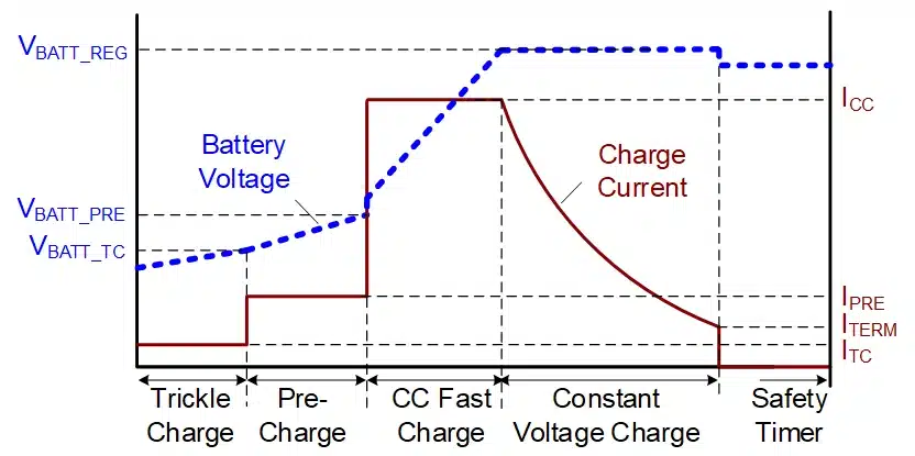
Pre-charge: When the battery voltage is too low, <3.0V, the charger will generally wake up the battery with a current rate of 0.1C until the voltage rises to 3.0V.
Constant current charging: This is the main charging stage. The battery is generally charged at a charging rate of about 0.5C. In this stage, the voltage gradually rises to 4.2V.
Constant voltage charging: When the battery voltage reaches 4.2 V, the charger switches mode and turns to a fixed voltage of 4.2 V. At this stage, as the battery becomes fuller, the charging current gradually decreases.
Charging cut-off: In the constant voltage stage, when the charging current is as low as 0.2C or 0.1C rate, the charger disconnects the charging circuit.
This is the complete CC/CV charging process and is the best way to charge the battery safely and efficiently.
An ordinary 5V USB charger cannot charge the battery directly. It cannot achieve current control in the constant current CC stage, nor can it accurately monitor current changes in the constant voltage CV stage. 5V voltage will cause overvoltage charging. Therefore, we always recommend a dedicated lithium battery charging circuit, such as TP4056, which can accurately execute each stage of CC/CV charging.
Charge management IC
The charging IC is mainly used to actively manage and control the entire charging process. It is responsible for executing the CC/CV process of the load, ensuring the safe and efficient charging of the battery and stopping at the appropriate time.
The protection IC passively monitors the entire battery status of the battery, and once it detects dangerous conditions such as overcharge, over discharge, over current, etc., it will immediately cut off the circuit. It is not responsible for the management process, it is more like a safety officer.
The two perform their respective functions without interfering with each other. The charging management IC has multiple intelligent functions as follows:
Voltage & Current Regulation: This is the core function, accurately implementing the CC/CV charging curve requirements.
Charging Status Indicator: Many ICs have pins that can drive an LED to tell you if the battery is charging, is fully charged, or if there is a fault.
Charging cut-off: Able to accurately detect when the current drops to the threshold in the CV stage and stop charging.
Safety Timer: Prevents accidental overcharging.
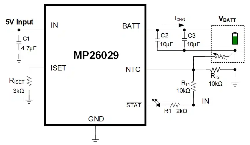
Temperature Monitoring (NTC): A thermistor can be connected to monitor the battery temperature and pause or stop charging if it is too hot or too cold.
The following are the mainstream charging IC categories on the market:
Linear Chargers: TP4056 and MCP73831/2 are very classic, commonly used, low cost, and simple peripherals, but the efficiency is relatively low and they tend to heat up when the charging current is large.
Switching Chargers: TI BQ24xxx and ADI/LTC LTC4xxx. The advantage of this type of IC is high efficiency (low heat generation), which is particularly suitable for applications that require large charging currents or have requirements for energy efficiency, but the circuit is relatively complex and the cost is a bit higher.
When choosing a specific charging IC, please consider the following factors:
How much charging current is needed? This directly determines the choice of linear and switching solutions.
What is the input voltage range? For example, 5V USB power supply, or other voltage.
Are there any additional requirements for charging efficiency and heat generation? High-current application products tend to use switching solutions.
Do you need additional functions? For example, temperature detection, status indicator light.
cost and circuit complexity.
Different roles of MOSFET in charging system
Our common 8205A MOS tube plays the role of a gatekeeper and is directly controlled by the protection IC, which is responsible for executing the circuit cutting action.
As the main power switch, in many charging circuits, especially the switching chargers mentioned above, and even in some linear chargers using external pass elements, the MOSFET acts as the main switching element. It is quickly turned on and off by the charging IC to efficiently regulate the voltage and current delivered to the battery according to the CC/CV charging curve. Its role here is active power regulation, not just passive safety cutoff.
Input Reverse Polarity Protection: A very common and clever use, especially at input connectors such as USB ports. Typically a single P-channel MOSFET is used. If the power is reversed, the MOSFET automatically remains off, preventing current from flowing in the reverse direction, thus protecting the entire device. This is a simple, reliable protection mechanism, separate from the functionality of a battery protection board.
These requirements may differ slightly from those required when selecting a MOSFET for a protection board.
Vds (maximum drain-source voltage): Must be able to safely withstand the highest voltage that appears in the charging circuit.
Id (maximum drain current): Needs to be able to withstand a continuous charge current, usually with enough safety margin.
Rds(on) (on-resistance): Mainly for the main power switch, because lower Rds(on) means higher efficiency and less heat generated during charging.
Vgs(th) (gate threshold voltage): It must be compatible with the voltage level provided by the charging IC or microcontroller that drives the MOSFET gate.
Designing the charging circuit
This is a complete connection diagram, the power flows from the adapter through the charging circuit we are designing, then enters the battery protection board, and finally reaches the battery cell. You can see the P+ and P- terminals on the protection board, which are the external connection points of the battery.
Below is a circuit for a very common TP4056 linear charging IC.
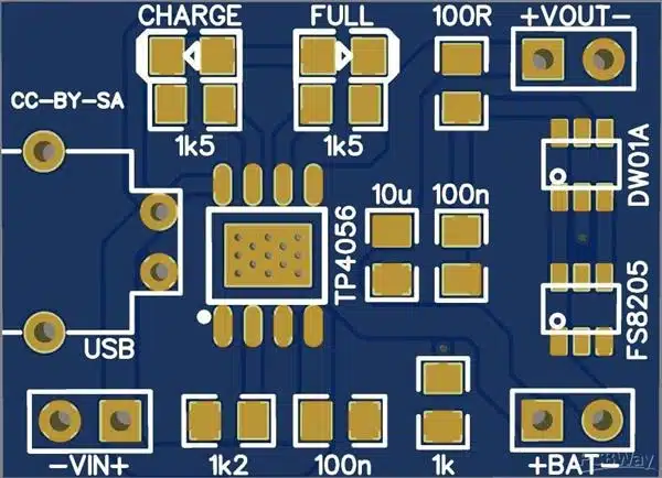
You can see the output pins of the TP4056 circuit, which are directly connected to the P+ and P- terminals of the battery pack.
The TP4056 circuit actively generates the required CC/CV charging curve, delivers current to the protection board, and then passes the current to the battery cell. At the same time, the protection board detects the voltage and current of the battery to prevent overcharging and overcurrent. The protection board plays a passive role in the charging process and only acts as a safety monitor, while the TP4056 performs the actual charging management.
Charging circuit component selection
To choose the best charging IC for you, you need to consider the following factors:
- What charging current is required? Corresponding to the input voltage range of the adapter, the charging voltage of a single battery is generally 4.2V.
- Choose a linear charging IC or a switching charging IC?
- Do I need an integrated MOSFET? Do I need a charging status indicator? What about NTC temperature sensing?
- Is the chip supply stable? Price? Packaging method, size, etc.
The withstand voltage (Vds) must be higher than the maximum system voltage, the rated current (Id) must be able to withstand the maximum operating current, the on-resistance (Rds(on)) is critical to efficiency and heat generation (the lower the better), the gate charge (Qg) affects the switching speed and drive loss, and the package is related to heat dissipation.
Next is the selection of peripheral passive components: capacitors, resistors, and inductors (only required for switching solutions).
Resistors: Mainly used to set charging current (such as Rprog of TP4056), voltage sampling and voltage division, etc. The key parameters are resistance value, accuracy (tolerance) and rated power. You can calculate the required resistance value according to the formula in the charging IC data sheet.
Capacitors: Used for input/output filtering, voltage stabilization, timing, etc. The key parameters are capacitance, withstand voltage, type (such as X5R/X7R ceramic capacitors, electrolytic capacitors, etc.) and equivalent series resistance (ESR).
Inductor (Switching Solution): It is the core energy storage component of the switching regulator. The key parameters are inductance value, saturation current (Isat) (must be greater than the peak current in the circuit), DC resistance (DCR) (affects efficiency, the lower the better), core material and size.
NTC thermistor: Common 10kΩ 8205B. The resistance value and B value determine the temperature change curve of the resistor.
Charging circuit PCB layout
We discuss some commonly used protection board PCB layout principles.
The power path, where current flows from the input to the charging IC and then to the output (P+/P-), should be as short and direct as possible, with minimal resistance and inductance, thereby reducing voltage drop, reducing heat, and improving efficiency.
Bypass capacitors are essential for filtering noise and stabilizing the power supply of ICs. They should be placed as close as possible to the IC power and ground pins they serve, and the connection paths should be short.
Thermal management, charging IC and MOSFET will generate heat when working, you can connect to the heat dissipation pad of the heating component through a large area of copper foil.
Grounding, a clean, low-impedance grounding is the basis for stable circuit operation. It can provide a uniform reference potential and a low-impedance return path.
We recommend that the traces connected to the P+ and P- terminals of the battery pack follow the power path principles mentioned above (short, wide, and straight).
If P+ / P- are brought out via connectors or pads, make sure those connection points themselves are strong enough to carry the expected charging current.
We recommend placing the output end of the charging circuit (where P+/P- is connected) at the edge of the PCB or a convenient location for connection, and as close as possible to the physical access point of the battery pack to shorten the external wiring.
If the NTC signal line is led out from the battery pack (or protection board) and connected to our charging circuit board, then the layout of this signal line also needs attention. It should be away from high current or switching noise paths to prevent interference and ensure accurate temperature readings.
Conclusion
In short, charging control is controlled by the charging IC, and battery protection is the responsibility of the PCM/BMS. Correctly selecting the charging IC according to your specific application requirements (current, voltage, function, etc.) is the first step to achieve expected performance and basic safety.
For Li-ion/Li-polymer batteries, we recommend battery packs with protection boards (PCM/BMS). If you would like to discuss more details, please contact us.