With the surge in demand for RV power system retrofits, the key is how to safely connect the RV battery. This article will provide a comprehensive analysis from industrial-grade standards, the steps for connecting a single 12V battery, and the design for expanding the capacity of a 24V/48V system, helping you achieve high-standard electrical integration.
Table of Contents
ToggleStandard Compliance & Pre-Installation Safety Specifications
The RV battery installation is an engineering project governed by international electrical and safety standards; it is a prerequisite for ensuring high efficiency and zero accidents.

- Industry regulations and standards:
RVIA & NFPA 1192: Specifies zoning, ventilation, and protective isolation standards for RV electrical systems.
NEC Article 551: Standardizes the installation location and grounding method for low-voltage DC cables, overcurrent protection devices, and other electrical components.
SAE Standard: Standardizes the mechanical shock resistance and temperature resistance of cables and connectors.
- Pre-installation safety protocols and personal protective equipment requirements:
Power off the system. In the event of an accidental short circuit, ensure all circuits are disconnected. During installation, you will need to use insulated wrenches, screwdrivers, sockets, and safety glasses. - Environmental inspection and battery preparation: Ensure the battery compartment temperature is not lower than 0°C, secure it with straps to prevent movement during vehicle operation, and check for oxidation of the terminals.
Wiring Specifications for Single 12V RV Battery Installation
The 12V battery is the foundation of the RV microstore system. You can install it according to the following parameters:
1. Wire gauge selection and voltage drop control. The AWG wire must match the maximum current and total line length. If the output current is 100A and the output distance is within 5 feet, we recommend using 2 AWG pure copper wire; if the output current is 200A, you can consider 4 AWG.
2. Overcurrent protection device. You must install an overcurrent protection device near the positive terminal. According to NEC and ABYC standards, the physical distance between the fuse and the battery positive terminal must not exceed 7 inches.
3. Terminal connection and torque specifications. You must use closed-end tinned copper terminals. The correct fastener stacking order is: battery pad/cylinder -> high-current cable terminal (Lug) -> low-current cable terminal (such as charger or light-load cable clip) -> flat washer -> lock washer -> nut.
Multi-Battery Bank Configurations
To meet the demands of high-power load operation, you can expand the battery capacity by connecting multiple battery packs in series and parallel. Here are the specific requirements:
1. Underlying compatibility principles before capacity expansion: Batteries with the same chemical system cannot be mixed. Batteries with the same rated capacity and voltage should ideally be from the same batch. Use identical wire diameters and lengths to avoid resistance differences.
2. Series and parallel connections: The former increases voltage, while the latter increases capacity. You can also create new battery packs through different series and parallel combinations. See more information.
3. Balanced wiring logic: Instead of connecting the total positive and negative terminals to the same first cell, a diagonal connection method is the most common. The total positive output line connects to the positive terminal of the first cell in the battery pack, and the total negative output line connects to the negative terminal of the last cell.
Connecting RV Batteries in Parallel
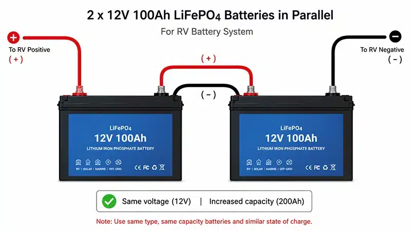
Parallel configuration is one of the most common capacity expansion methods in RV electrical systems. Connecting the positive terminals of multiple batteries to each other, and the negative terminals to each other, only increases capacity without changing the voltage. The following example uses two standard 12V 100Ah LiFePO4 batteries connected in parallel:
Securely install the batteries in their physical mounting slots, leaving a 0.5-inch gap between them for heat dissipation.
Fabricate equal-length bridge wires, matching the main output wires (2 AWG). Precisely measure the physical length of each bridge wire to ensure absolute equality.
Interconnect the positive and negative terminals by connecting the positive terminals of the first and second batteries using the red bridge wires.
Connect the diagonal main output wires by connecting the total positive main output wire leading to the RV inverter to the positive terminal of the first battery, and the total negative main output wire to the negative terminal of the last battery.
Connecting RV Batteries in Series
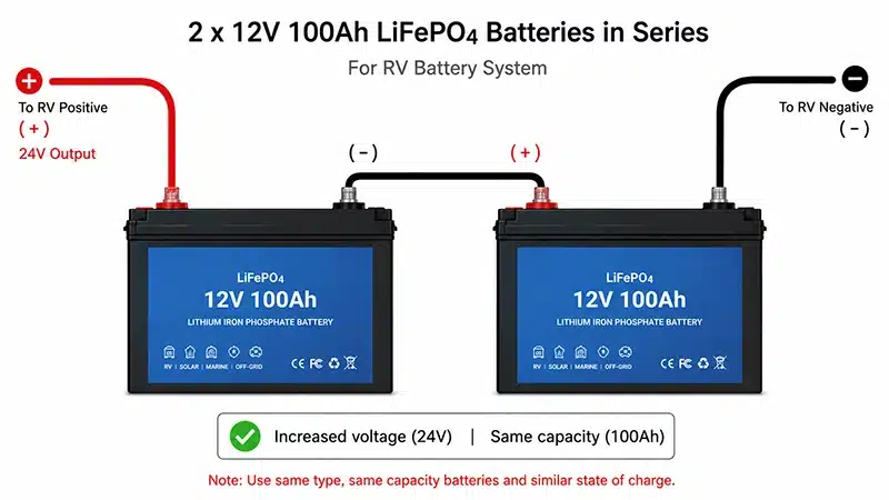
Unlike parallel configurations, series configurations connect the negative terminal of the first battery cell to the positive terminal of the second, thus doubling the total system voltage. The following example uses two standard 12V (12.8V) 100Ah LiFePO4 batteries connected in series:
First, pre-balance the batteries to ensure the system voltage (SoC) of both cells is consistent, with a voltage difference of less than 50mV.
Use pure copper-tinned wire to securely connect the negative terminal of the first battery cell to the positive terminal of the second battery cell.
Connect the system’s overall positive terminal to the positive terminal of the first battery cell, and connect the system’s overall negative terminal to the unconnected negative terminal of the last battery cell.
Best Practices for RV Battery Interconnection
RVs operate in environments characterized by constant bumps, high vibrations, and fluctuating temperature and humidity. Even minor oversights in interconnections can lead to system malfunctions.
Physical and electrical consistency of wiring is crucial. All battery pack connection wires must have identical resistance, wire diameter, length, terminal material, and crimping process.
Corrosion and anti-loosening protection of contact surfaces is essential. A thin layer of professional electrical anti-oxidation grease should be applied to the clean, tinned copper terminals and battery terminals.
Thermal and mechanical protection is vital. All exposed terminals of interconnecting wires, busbars, and main fuse holders must be fitted with dedicated insulating protective covers.
Busbar vs Cable Interconnections
Below is a comparison table of traditional heavy-duty cables and solid busbars:
Solid busbars are suitable for high-capacity batteries (>300Ah), and their internal impedance consistency far exceeds that of manually crimped cables.
Flexible cables are suitable for RV conversions; thanks to their natural flexibility, they can easily absorb vibrations and shocks from the RV.
| Compare | Heavy-Duty Cables | Solid Busbars |
|---|---|---|
| Space & Layout | It is bulky, requires a large bending radius, and appears cluttered. | It has a compact, flat structure, is standardized, and exudes a high-end feel. |
| Current & Cooling | The heat dissipation is relatively poor. | Excellent heat dissipation. |
| Installation Cost | Materials are cheap initially, but labor is expensive. | The initial mold making is expensive, but the assembly is extremely fast. |
RV Battery Connection Diagrams & Technical Engineering Support
A clear and standardized RV battery connection diagram is a universal standard for installation and after-sales service.
Industrial-grade wiring diagrams must include battery interconnections (full view), clearly labeling the complete chain of battery packs, fuses, system shunts, MPPT solar charge controllers, bidirectional inverters/chargers, and the vehicle’s heavy-duty DC power distribution panel.
To meet the power needs of different levels of RVs, Hongyitai offers 12V, 24V, and 48V RV batteries. Our engineering team can customize a 2D/3D RV battery connection diagram specifically for your brand, based on your RV’s dimensions, battery compartment dimensions, and specific electrical load requirements.
FAQs
Reversing the positive and negative terminals of a battery is an extremely dangerous action that may damage the MOSFET on the battery protection board. If the BMS does not intervene in time, it may even lead to a short circuit, smoke, or thermal runaway. Before connecting the battery, always carefully check the polarity markings (+/-).
This is caused by inrush current (capacitor discharge). When connected to an inverter, controller, or load, this instantaneous high-current charge occurs. This brief surge of high current ionizes the air before it comes into contact with a metal surface, thus generating a spark.
Generally speaking, there are no fixed series and parallel connection limits for standard lithium iron phosphate battery packs. We can produce 12V, 24V, 36V, 48V, 72V, and even larger batteries for you.